Revit-Built Mechanical Models and Full Clash Coordination —
From HVAC and Pipework to Plant Rooms and Construction
Release
Mechanical systems represent a significant share of any building’s programme and cost. When models are built accurately and coordinated from the outset, installation is predictable. When they are not, site conflicts and rework affect every trade that follows.
At Bimacme, we build Revit mechanical models from design drawings, specifications, and equipment data then coordinate them against all building disciplines using Navisworks. No zone is issued for construction until it is fully clash-free and signed off.
From Drawing to Installation-Ready Model Body
We build mechanical models that reflect how systems will be installed, not just what the designer intended. Equipment dimensions, clearances, and access routes are correct before coordination begins.
Clashes Found in the Model, Not on Site Body
HVAC routes that conflict with structural beams, pipework that crosses ceiling voids, and plant that blocks maintenance access are all identified and resolved in the model before any material is ordered or installed.
A Construction Release You Can Build From Body
Each coordinated zone is formally signed off with a clash resolution log, coordinated drawings, and a sleeve and penetration schedule. Your installation team starts with clarity.
Our scope covers the full mechanical BIM cycle from initial model build and internal QA through to multi-discipline coordination, construction release, and shop drawing production.
We build HVAC ductwork, pipework, plant equipment, and all mechanical accessories in Autodesk Revit to the agreed LOD, using manufacturer data and project specifications to ensure every element is dimensionally accurate.
Supply, return, exhaust, and specialist ductwork routes are laid out with correct sizes, slopes, insulation allowances, and elevation data coordinated against ceiling zones and structural constraints from the start.
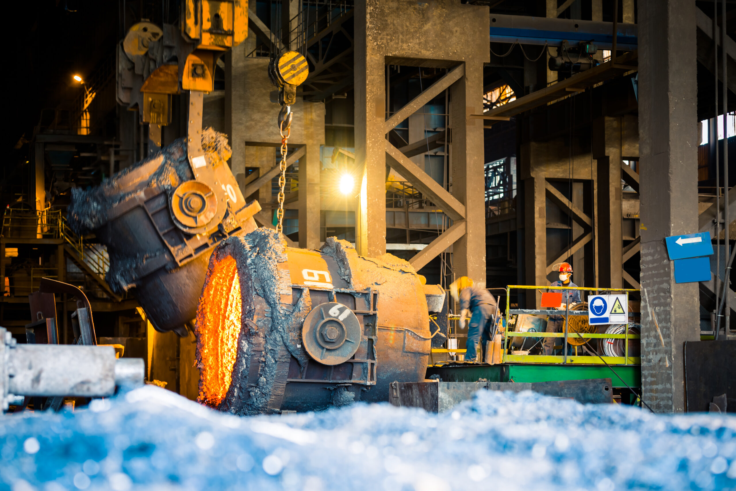
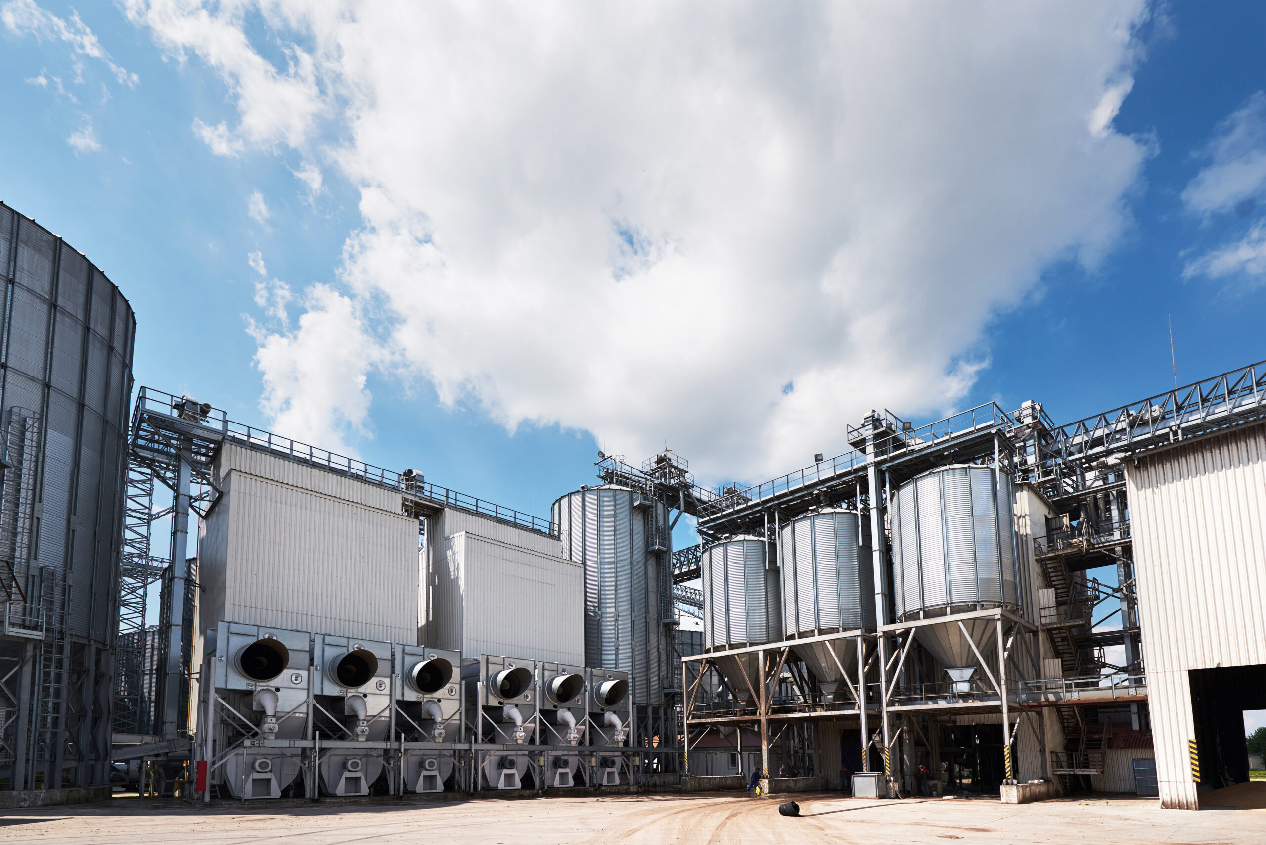
Boilers, chillers, AHUs, pump sets, buffer vessels, and associated pipework are modelled in plant room environments with verified maintenance clearances and access requirements checked against building regulations.
The mechanical model is clash-tested against all building disciplines using Navisworks. Every conflict is catalogued, assigned to the responsible party, and tracked to resolution before the zone is released for construction.
Mechanical penetrations through walls, floors, and structural elements are identified, sized, and scheduled ahead of structural works eliminating reactive core drilling and the programme delays that follow.
Installation-ready shop drawings are produced directly from the coordinated Revit model including duct layout plans, plant room drawings, reflected ceiling coordination drawings, and hanger and support details.
We model the full range of mechanical building systems. The table below sets out what each system includes in our scope and what the primary coordination deliverable is for each.
Mechanical System | What Is Modelled | Key Deliverable |
HVAC Ductwork | Supply, return, exhaust, and fresh air ductwork including smoke extract routes, duct sizes, insulation allowances, and elevation data | Coordinated duct layout drawings and clash-free routing model |
Air Handling Units (AHUs) & FCUs | Full equipment bodies with correct dimensions, maintenance clearances, access zones, and connection points to ductwork and pipework | Equipment layout sheets, access clearance documentation |
Chilled & Hot Water Pipework | Chilled water flow and return, heating circuits, condensate drainage, and pressurisation lines with correct pipe sizes, gradients, and valve positions | Piping isometrics, spool references, and coordinated routing model |
Mechanical Plant Rooms | Complete plant room layouts including boilers, chillers, cooling towers, pump sets, buffer vessels, and associated pipework and valve arrangements | Plant room coordination drawings and clearance-verified 3D model |
Ventilation & Pressurisation Systems | Stairwell pressurisation, corridor ventilation, toilet and kitchen extract, car park ventilation, and louvre positions relative to structure and facade | Ventilation layout drawings and structural penetration schedule |
Mechanical Accessories | Volume control dampers, fire dampers, smoke dampers, diffusers, grilles, attenuators, flexible connections, and associated hangers and supports up to LOD 400 | Accessory schedules, hanger and support details, reflected ceiling drawings |
Refrigerant & Gas Systems | Refrigerant pipework for split and VRF systems, gas supply distribution, meter positions, and isolation valve locations | Refrigerant pipe routing drawings and gas riser coordination model |
Underfloor Heating & Radiant Systems | Underfloor heating manifold positions, circuit layouts, screed depth allowances, and coordination with structural slab build-up | UFH layout drawings, manifold locations, slab interface notes |
Our mechanical modelling and coordination process follows the same structured sequence on every project. Each step has a defined output that feeds directly into the next, so there are no gaps between model build, internal review, coordination, and construction release.
We receive architectural, structural, and mechanical design drawings or existing Revit models. Files are reviewed for coordinate alignment, scope boundaries, and any BEP requirements before modelling begins.
HVAC ductwork, pipework, equipment, and accessories are modelled in Autodesk Revit to the agreed LOD. Equipment dimensions are sourced from manufacturer data sheets where available. Every element is positioned to reflect real installation conditions, not just design intent.
The mechanical model is linked with architectural, structural, electrical, plumbing, and fire protection models in a single Navisworks or Revit environment to enable multi-discipline clash testing.
Clashes between the mechanical model and all other disciplines are identified and catalogued. Reports are issued to the responsible parties with clash location, severity, and a suggested resolution path.
We attend and support weekly coordination meetings, working through the clash matrix with trade representatives. Model updates are made following agreed resolutions, and re-testing is carried out to confirm each fix.
Once the mechanical model is fully coordinated and all clashes are resolved and signed off, the model and associated drawings are issued for construction with a complete coordination record.
You need a model that reflects how your systems will actually be installed, not a design-intent drawing converted to 3D. We build mechanical models to the LOD your installation team can work from with correct equipment clearances, hanger positions, and sleeve openings already coordinated before site mobilisation.
Mechanical clashes discovered on site create programme delays that affect every other trade. We give you a signed-off, clash-free mechanical model for each coordinated zone, with full documentation to hold subcontractors accountable to a single agreed installation layout.
When your design reaches the coordination stage, we translate your engineering intent into a construction-ready model. We work from your drawings, specifications, and equipment schedules to build a model that passes coordination without requiring design rework.
Mechanical systems represent a significant portion of building cost and programme risk. A coordinated mechanical model reduces that risk by catching conflicts early, reducing change orders, and ensuring your contractor is working from a single agreed model rather than managing conflicts in the field.
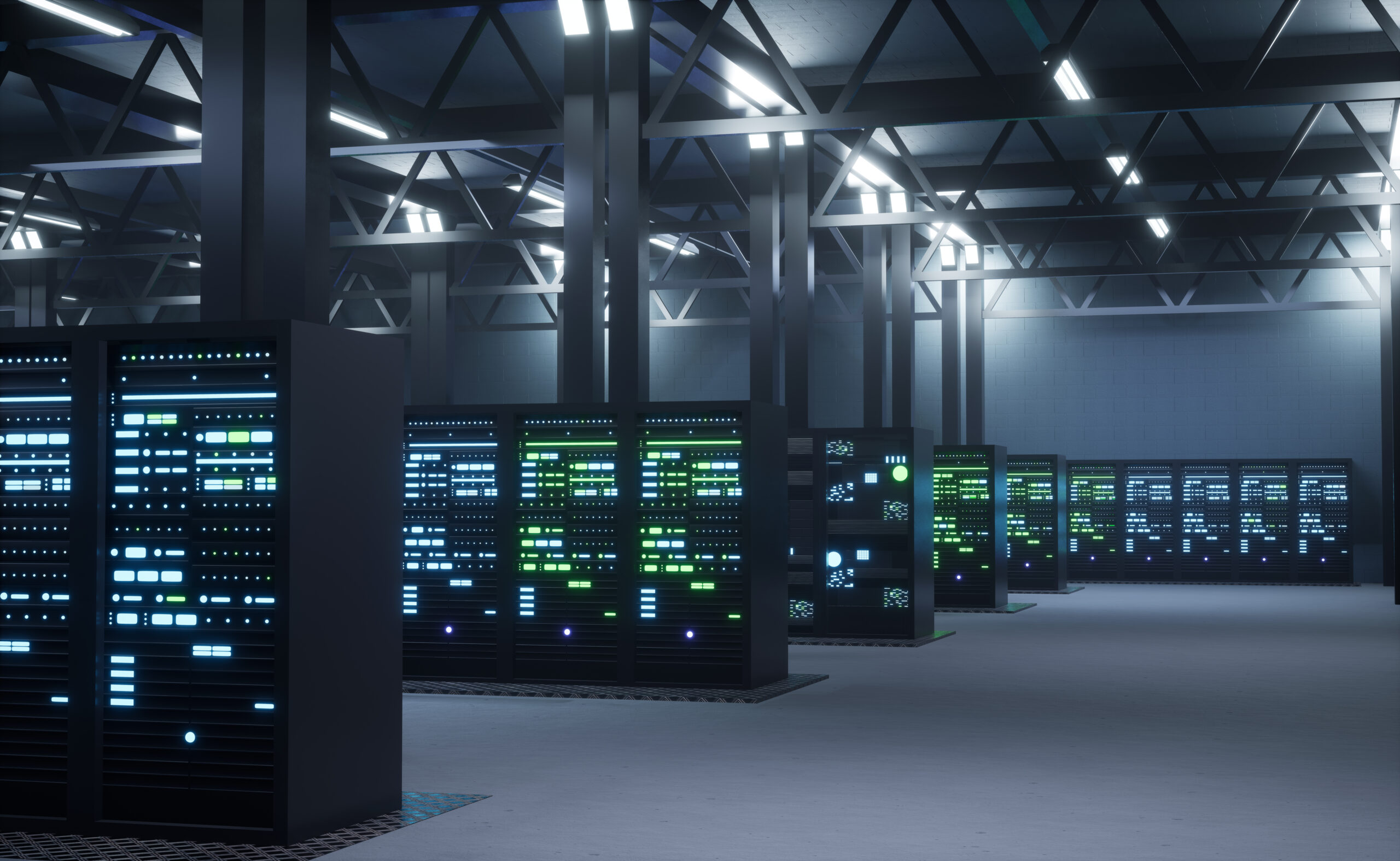
We deliver mechanical BIM modelling and coordination for projects ranging from residential developments and commercial fit-outs to healthcare facilities, data centres, and large-scale infrastructure programmes.


Share your project details and we will respond with a scope and timeline within 48 hours.
Mechanical BIM Modelling is the process of building a detailed 3D model of all mechanical systems HVAC ductwork, pipework, plant equipment, and accessories using software like Autodesk Revit. The model includes equipment data, routing logic, maintenance clearances, and coordination information that installers need on site.
Mechanical Modelling builds the 3D model of the mechanical discipline. Coordination takes that model and resolves how it fits alongside structural elements, architectural ceilings, electrical trays, plumbing, and fire protection using clash detection tools like Navisworks. Both are needed a well-built model without coordination can still produce installation conflicts on site.
LOD 350 is the standard for construction release. It includes support and hanger positions, sleeve locations, and service zone clearances that trades need to install without on-site problem-solving. LOD 300 is suitable for design checks only and should not be used as the basis for trade installation.
We model HVAC ductwork, AHUs, FCUs, VAV boxes, chilled and hot water pipework, plant room equipment, ventilation, pressurisation systems, refrigerant and gas pipework, underfloor heating, and all associated accessories including dampers, diffusers, and support steelwork.
Yes. We work from 2D CAD drawings, PDF design sets, equipment schedules, and specifications. Where design information is incomplete, we flag the gaps formally so they are resolved before the model reaches coordination not discovered on site.
Clashes with structure, ceiling conflicts, missing sleeve locations, and equipment clearance issues are resolved in the model weeks before site mobilisation. A conflict fixed in the model takes hours; the same conflict found during installation can take days and delays every trade that follows.
Yes. Once coordinated and signed off, we produce installation-ready drawings directly from Revit including duct layout plans, section and elevation views, plant room drawings, reflected ceiling coordination drawings, and sleeve and penetration schedules.
Yes. We review the existing model against current design information, identify what needs rebuilding or updating, and take coordination forward from that point. We document the model’s condition at handover so the project team has a clear record of what was inherited and what we coordinated.